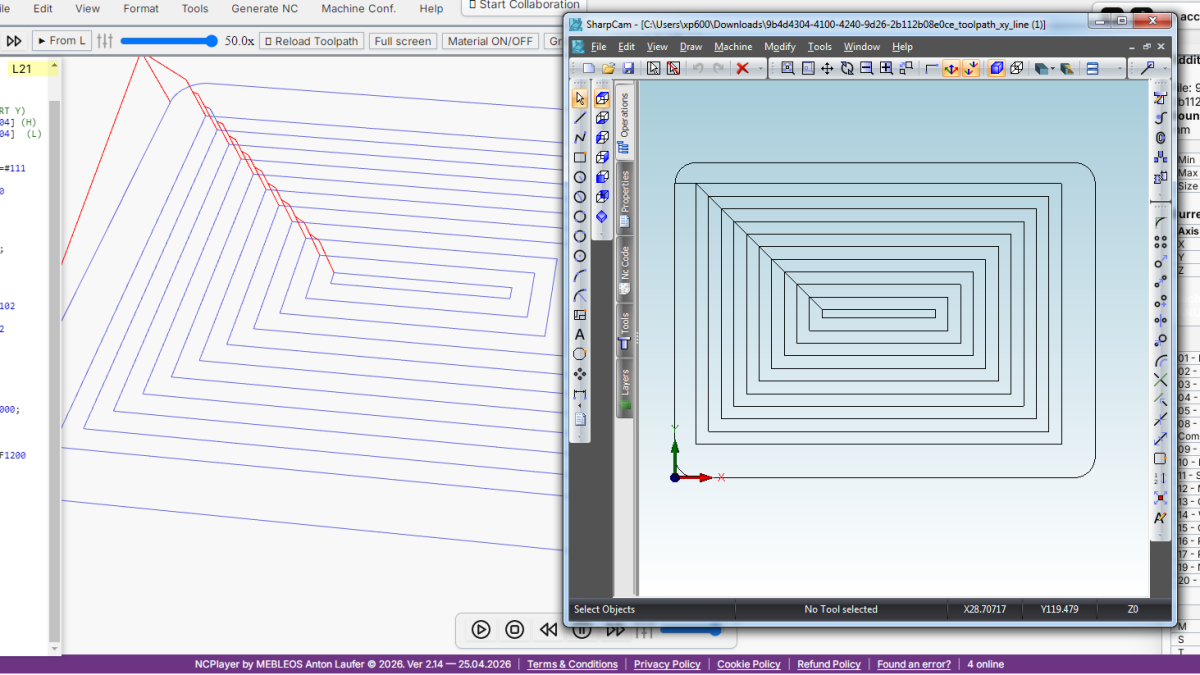
NCPlayer is an online CNC simulator and G-code debugger by CNC Passport. One of the practical NCPlayer functions is exporting the simulated toolpath to DXF. This is not just saving an image from the screen: NCPlayer takes the calculated toolpath after simulation and creates geometry that can be opened in a CAD/CAM system, checked as a contour, sent to a colleague, or used as technical evidence of the machining result.
The function is especially useful when G-code must not only be run in a simulator, but also quickly shown as understandable geometry: to a programmer, setup operator, technologist, inspection engineer, or customer.
Why export a CNC toolpath to DXF
In production practice, G-code often exists separately from the CAD model. A program may be written manually, changed at the control, generated by a macro, received from another contractor, or adapted for a specific machine. In these cases it is important to answer a simple question quickly: what actual path will the tool follow?
DXF helps show this toolpath in a familiar engineering environment. The file can be opened in a CAD program, overlaid on the part contour, compared with a drawing, used to check machining levels, and used to show movements without opening the NC code itself.
DXF export in NCPlayer is useful for several tasks:
- quick geometry verification after simulation;
- comparison of the toolpath with the original part contour;
- documenting the result of NC program verification;
- analysis of programs where the toolpath is created by macros, cycles, or repeated passes;
- preparing an understandable file for discussion between the programmer, operator, and technologist.
How Export DXF works in NCPlayer
Export DXF uses the simulation result rather than the source program text directly. This distinction matters. NCPlayer first processes the G-code, builds the tool motion path, takes the selected controller into account, and only then exports the calculated segments to DXF.
That is why the simulation must be run before exporting. If the toolpath has not been built yet, there is nothing useful to export. This approach reduces the risk of getting a visually clean but incorrect DXF that does not reflect the actual tool motion after processing macros, repetitions, coordinate modes, and controller-specific behavior.
A typical workflow looks like this:
- Open or paste an NC program in NCPlayer.
- Select the required controller or simulation mode.
- Run the simulation and make sure the toolpath is built.
- Open the File menu and choose toolpath export to DXF.
- Adjust DXF Export Settings if needed.
- Download the DXF file and open it in CAD/CAM or pass it on.
What exactly goes into the DXF
The DXF contains the toolpath geometry calculated by NCPlayer. Depending on the selected setting, this may be a set of LINE segments or POLYLINE entities. This format is convenient for viewing, checking, and later engineering analysis.
The DXF file can include cutting moves and, when needed, rapid moves. Rapid moves are often useful during diagnostics: they show where the tool transfers between machining zones, where a collision risk may exist, or where the program makes an unexpected transition. For a clean geometric contour, however, rapid moves can be excluded.
NCPlayer can also organize the toolpath by layers. This helps avoid mixing all geometry into one set of lines and instead separate it by meaning: for example, by movement type or by Z level.
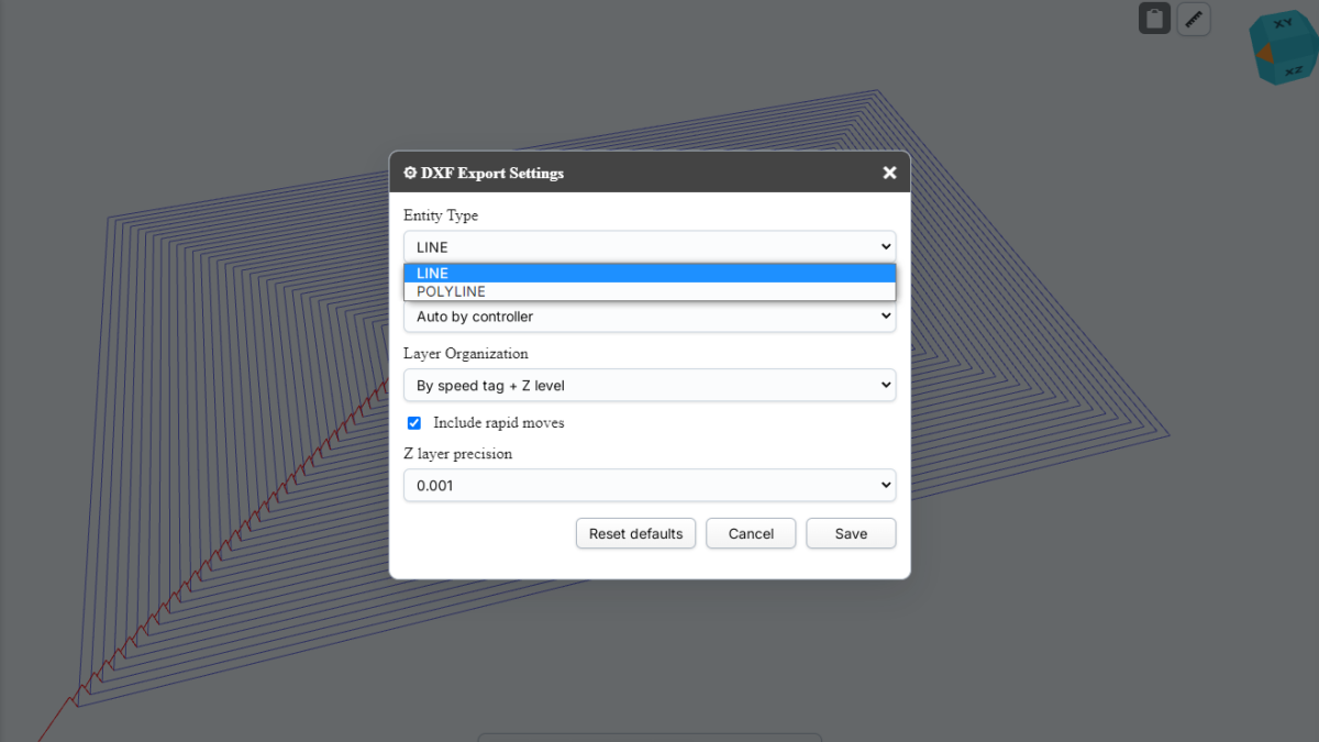
DXF Export Settings
NCPlayer has a separate DXF Export Settings dialog. It controls how the file will be generated.
Main parameters:
- Entity Type: selection between LINE and POLYLINE;
- Projection: automatic or manual toolpath projection;
- Layer Organization: layer organization method;
- Include rapid moves: include or exclude rapid movements;
- Z layer precision: precision for grouping Z levels.
These settings matter because the same NC code can be used for different verification tasks. Sometimes the user needs the simplest possible DXF with one geometry set. In other cases it is better to separate the toolpath into layers to see cutting and rapid moves separately or to understand which Z levels were used for passes.
LINE or POLYLINE: what to choose
The LINE format creates separate segments between toolpath points. It is a simple and compatible option that works well for verification, import into different CAD systems, and analysis of individual segments.
POLYLINE connects points into polylines. This option may be more convenient when a more compact toolpath structure is needed and the geometry should be handled as continuous movement chains.
In practice, this rule is useful:
- LINE when maximum compatibility and simple diagnostics are required;
- POLYLINE when more continuous geometry and convenient work with movement chains are important.
Projections: XY, XZ, YZ, and XYZ
NCPlayer supports different projection modes for DXF. Automatic mode selects the suitable plane by controller type: XY is usually used for milling, while XZ is more logical for turning. The user can also choose the plane manually when needed.
Available options:
- Auto by controller;
- XY;
- XZ;
- YZ;
- XYZ.
For milling programs, XY is most often needed because the main part geometry usually lies in that plane while Z represents machining depth. For lathe programs, the XZ plane is often important because the part profile is built relative to the spindle axis. XYZ is useful when the spatial character of the toolpath should be preserved rather than reduced to one plane.
DXF layers: why they matter
Layers help turn the export from a simple set of lines into a more readable engineering structure. In NCPlayer, the user can choose a single layer or separation by toolpath attributes.
Layer organization options:
- Single layer: the whole toolpath in one layer;
- By speed tag: separation by movement type, for example rapid and cut;
- By Z level: separation by Z levels;
- By speed tag + Z level: combined separation.
The most practical mode for analysis is often separation by speed tag and Z level. It shows where rapid moves were used, where cutting passes were made, and at which depths machining occurred. A single layer is enough for a rough preview, but layers provide much more information when investigating errors.
A practical use case
Imagine a programmer receives an NC program with repeated passes and macro logic. At first glance, it is difficult to understand the final toolpath from the G-code text: some coordinates are formed through variables, some passes repeat, and the movement depends on the selected controller.
In NCPlayer, the user can first run the simulation, then export the toolpath to DXF and open the result in CAD. After that it becomes easier to check:
- whether the toolpath matches the expected contour;
- whether there are unnecessary passes;
- whether repeated sections were processed correctly;
- whether rapid moves entered unsafe zones;
- whether Z levels match the expected machining strategy.
This process does not replace full technological verification, but it significantly speeds up initial analysis and communication between production team members.
How Export DXF differs from saving the NC program
Saving the NC program saves the G-code text. Export DXF saves the geometric result of the simulation. These are different tasks.
The NC file is needed for the machine, editing, and storage of the control program. DXF is needed for viewing, comparison, and engineering exchange. That is why DXF export is especially useful when a person needs to understand the shape of the toolpath quickly, rather than read every line of the program.
For example, a G-code line may be technically valid, but the final toolpath may still be unexpected because of an active coordinate mode, compensation, macro variable, cycle, or selected arc interpretation. Simulation followed by DXF export helps show the result at the movement level.
Where this helps the team
For a CNC programmer, Export DXF is a way to quickly verify that the program produces the expected geometry. For an operator, it is a way to see the toolpath without deep code analysis. For a technologist, it is a way to compare motion with a drawing or operation sheet. For a production manager or recruiter evaluating a CNC specialist's skill, it is an additional visual artifact: it shows not only that a person wrote G-code, but also what result that code creates.
CNC Passport is a professional CNC ecosystem developed by MEBLEOS. In this ecosystem, NCPlayer serves as a practical tool for simulation, verification, and explanation of CNC programs. Export DXF extends that role: the simulation result can be taken out of the browser and used in a familiar engineering workflow.
Limitations and correct expectations
DXF from NCPlayer should be treated as an export of the simulated toolpath, not as a complete CAM model of the part. It shows the tool path calculated by the simulator and helps analyze movement. It does not replace the postprocessor, technological documentation, fixture verification, machine kinematics checks, or real machining conditions.
To get a useful DXF, several rules matter:
- run the simulation first instead of exporting an empty program;
- choose the correct controller or interpretation mode;
- use the appropriate projection for the milling or turning task;
- include rapid moves for diagnostics, but disable them for a clean contour;
- use Z layers when pass depths need to be analyzed.
Conclusion
Export DXF in NCPlayer makes simulation more useful for a real CNC team. The user gets not only a visual toolpath in the browser, but also a DXF file that can be opened in CAD/CAM, checked, compared, shared, or attached to a technical discussion.
For programs with macros, cycles, repeated passes, and controller-specific behavior, this is especially valuable: NCPlayer first calculates the actual toolpath and then exports it as engineering geometry. This helps find errors faster, explain the result more precisely, and work with G-code more confidently before running the program on a machine.